Description and Usage Instructions
DESCRIPTION
The Robust Automatic Detection in Laser Of Calibration Chessboards
(RADLOCC) toolbox allows for the automatic extrinsic laser-camera calibration.
The toolbox provides the RADLOCC algorithm which automatically extracts the
calibration board lines from the laser scan. This algorithm was added onto the
original Laser-Camera Calibration Toolbox by Fabio Ramos and James Underwood.
The calibration process used in the toolbox is based on [1]. The method
requires a calibration plane (such as a chessboard) to act as a common dataset
between the laser range finder and the camera. The points in the laser scans
corresponding to the calibration plane need to be selected. Using the RADLOCC
algorithm [2], these points are extracted automatically. The toolbox assumes
that the intrinisc parameters already exist. For automatic camera calibration
check the RADOCC toolbox.
CONTENTS
The toolbox provides the following functionality:
- Automatic selection of board lines.
- Automatic guess of initial estimate (manual input of initial estimate is
also possible).
- Optional manual selection of board lines.
- Extrinsic laser-camera calibration.
- Calibration error analysis and improvement.
The toolbox provides a GUI for the user's convenience.
REQUIREMENTS
The toolbox has the following requirements:
- The toolbox assumes that camera calibration has already been performed.
Refer to the RADOCC toolbox for automatic camera calibration.
- The toolbox relies on a calibration plane to act as a common dataset
between the camera and the laser range finder. It is assumed that the
camera calibration provides the orientation and position of the calibration
plane.
- It also requires that changes to the background to remain as minimal as
possible. This is required for the automatic selection process.
- It is recommneded that the calibration board not be rotated more than 45
degrees about its orthogonal axis.
- Finally, the board's position should be moved around as much as possible
throughout the dataset.
INSTALL
After unzipping the file to folder installfolder, add the
directory to the Matlab path:
>>addpath('installfolder'); savepath;
GETTING STARTED
To begin the calibration, set the Matlab path to the path containing
the laser data and the file 'Calib_Results.mat' output by the camera
calibration. Then, type RADLOCC at the Matlab command
line.
The following dialog should pop up.
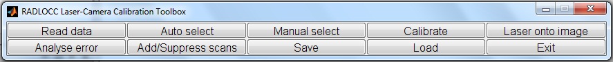
The following steps introduce a quick start to performing a
calibration:
- Press Read data. Enter the file names (Refer to the DATA FORMAT
section for details about the format of the calibration dataset). Reading
the data may take some time depending on the size of the data. Fortunately,
after the data is read, the user can press Save to save the data
and use Load next time for quicker loading times.
- Press Auto select. The program will ask for two threshold
values: rough line threshold and fine line threshold. The line extraction
stage of the automatic selection process requires two thresholds. The rough
threshold is used for obtaining the intial estimate for the calibration and
the fine threshold is used for the final optimisation. The selection of
these values will depend on the quality of the laser range finder, the
default values should be fine for a SICK laser. The program will then ask
whether the user wants the program to attempt to guess the initial
estimate. Select yes or manually enter the intial estimate. The
program will then run an optimisation to find the boards in the laser
scans. Finally, the user might be asked to verify some lines suspiciously
extracted and/or to manually select the board from laser scans with no
boards extracted.
- Press Calibrate to obtain the calibration results with
uncertainty. The uncertainty values represent the estimated standard
deviation of the errors.
- The calibration process should be complete; however, there might be need
for refining the calibration. For visual inspection, press Laser onto
image to reproject the laser scans onto the images.
- The Analyse error feature displays the error for each extracted
board. This feature can be used with Add/Suppress scans option to
remove outlier scans.
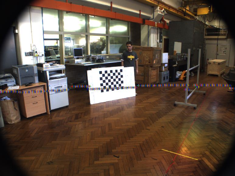
- Verify the results by reprojecting the laser scans onto the images. This
can be done by pressing Laser onto image and then selecting the
image numbers. What is important to notice is the consistency between the
range jumps of the laser scan and edges in the image as shown below.
IMPROVING THE CALIBRATION
The calibration results can be adjusted/improved by one of the
following methods:
- Manually selecting some boards in the laser scans at the end of the
automatic selection process. The auto selection process might remove some
valid board scans. This reduce the amount of data available for
calibration. Manually selecting these scans might improve the calibration
resutls.
- Suppressing outlier scans. For various reasons, some scans might appear
as an outlier while analysing the errors. Suppressing these scans might
improve the results.
- Changing the line thresholds. The default line thresholds were tuned for
SICK lasers. The accuracy of other laser range finders might differ.
Therefore, the toolbox might fail to detect laser boards in such scans. Two
thresholds are used, rough and fine. The rough threshold is used to permit
the program to successfully obtain an initial estimate for the calibration
since a fine threshold might remove alot of board points. The fine
threshold on the other hand, is used to remove noise from board scans and
reduce error in the calibration.
- By choosing to Manually select (this does not use any automatic
extraction) the laser board scans.
DATA FORMAT
The Laser data file is assumed to be in ascii format. Two files are
expected. The first file contains the laser range data. The second file
contains the timestamps of the images used in the camera calibration. In the
first file each row should correspond to a laser scan. The format of each line
should be as follows:
<timestamp> StartAngleRads AngleIncrementRads EndAngleRads
RangeUnitType NoAngles [Ranges]
The second file contains the timestamps for the images used in the
camera calibration sorted in a column.
RangeUnitType
= 1 for mm
= 2 for cm
= 3 for m
= 4 for km
CALIBRATION PARAMETERS
A point in 3D space with coordinate vector Pc with
respect to the camera has coordinate vector Pl in the laser frame.
The two vectors can be related by the following
equation:
Pl=Φ(Pc-Δ)
where Δ is the translation offset
and Φ is the rotation matrix defined by the set of three
Euler angles φx, φy and
φz.
Φ defines the rotation that takes the camera frame to the laser
frame. It is a combination of three rotations (the order is important). The
first is a rotation about the x axis by the angle
φx, the second is about the (possibly new) y
axis by the angle φy and the last is that about
the (again possibly new) z axis by the angle
φz. Δ is simply the
coordinates of the vector extending from the camera origin to the laser origin
in the camera’s coordinate frame.
CONTACT
If you have a question or a suggestion, or if you find a bug, please email
Abdallah Kassir.
References:
1. Qilong, Z. and Pless, R. Extrinsic calibration of a camera and laser
range finder (improves camera calibration), IROS 2004.
2. Kassir, A. and Peynot, T. Reliable Automatic Camera-Laser Calibration,
Australasian Conference on Robotics and Automation 2010.